Introducing the Desk Buddy - your new study companion that not only helps you protect your eyesight but also reminds you to take breaks after prolonged periods of studying. As we all know, prolonged periods of screen time can have a negative impact on our health, and that's where the Desk Buddy comes in. My product is designed to detect the distance between the user and their computer and change color accordingly, reminding the user to maintain a safe distance from their screen. In addition, it also has a built-in timer that reminds users to take regular breaks, promoting healthy study habits and overall wellbeing.
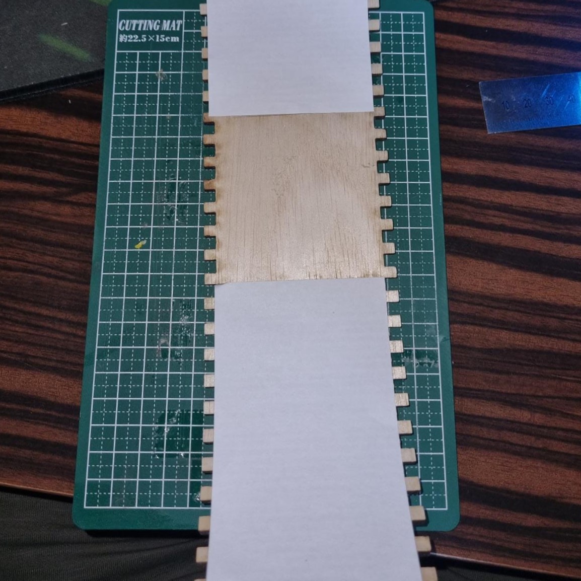
During the design process ideation stage, I took inspiration from a previous design and decided to combine two ideas together: the finger joint and the living hinge. To do this, I used the concept of a jewelry box holder and incorporated finger joints to make a casing that curves and joins together in an aesthetically pleasing way. I then utilised the living hinge concept to add flexibility and mobility to the structure.
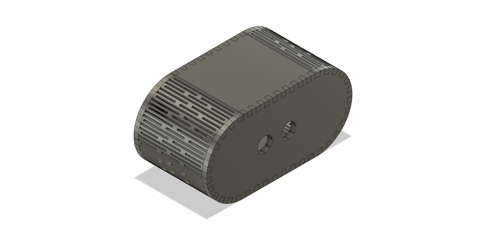
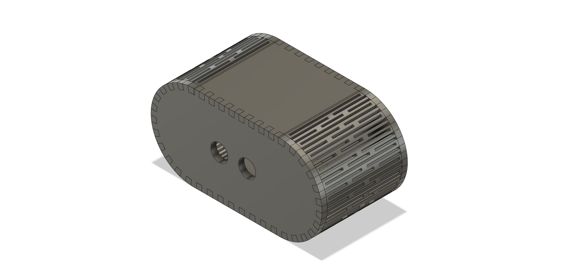
To bring my idea to life, I used Fusion 360 as my CAD software and specifically utilized the sheet metal and extrusion functions. These features helped me create the desired shape and structure of the casing, while also allowing me to easily make adjustments to the design as needed. With Fusion 360, I was able to visualize the final product and ensure that all the components would fit together perfectly before beginning the fabrication process.
A rough sketch of my product, including its key features and components.
The sketch show the product from various angles, highlighting its proportions. It may also include notes or labels that describe specific elements of the product, such as buttons, screens, or connectors. The sketch is usually not a final design, but rather a starting point for further refinement and development.
As seen, I wanted to incorperate a slot for a acrylic light to be used as a place to take notes however I thought back to its most basic form, my product is a study aid to promote studying and a acrylic might be too distracting and I didn't incorperate into the final design
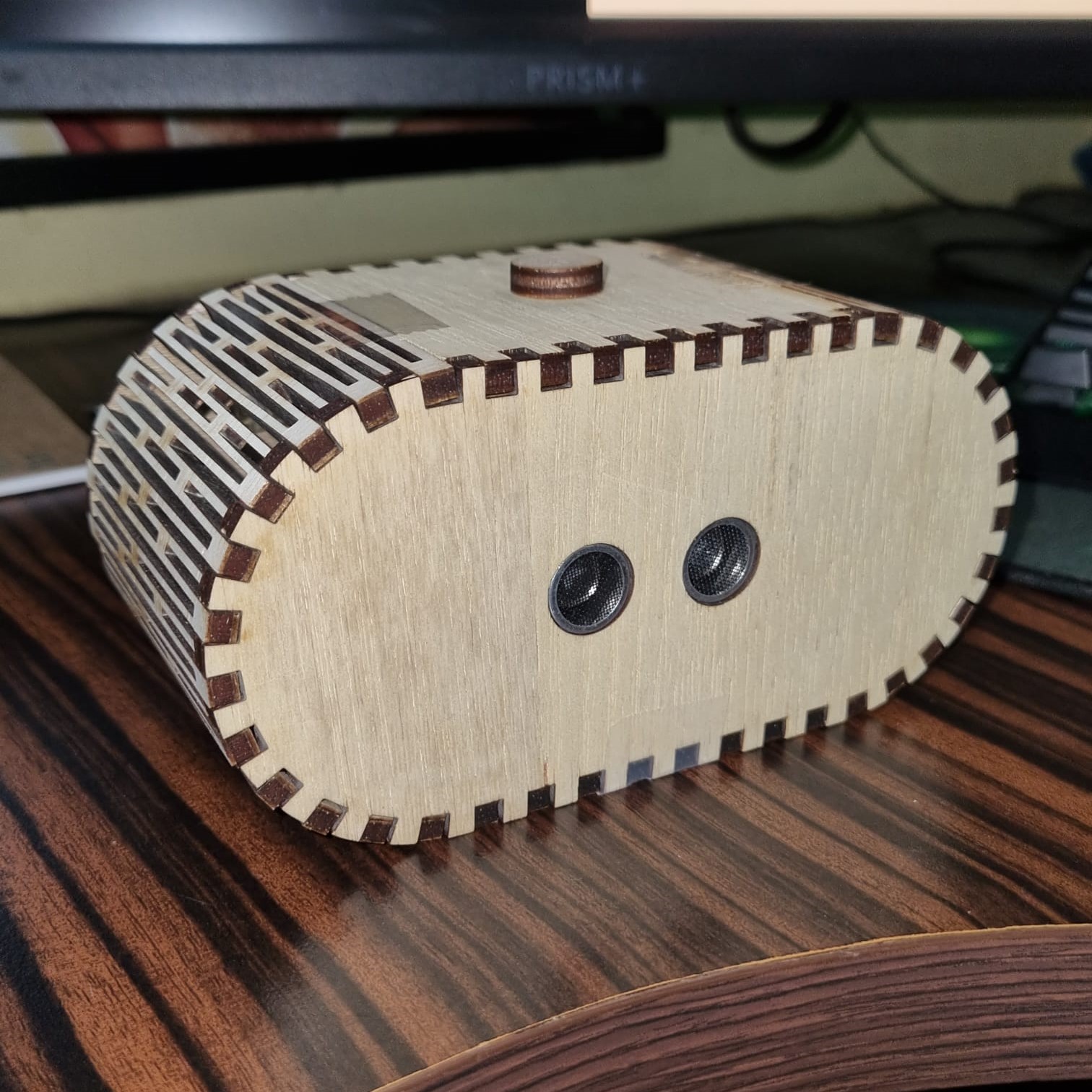
The circuitry of the product includes an ultrasonic distance sensor that is connected to the Arduino board. The sensor sends out ultrasonic waves and measures the time it takes for the waves to bounce back. Based on this time, the sensor can calculate the distance to an object in front of it.
The Arduino board then uses this information to control the neopixel light strip. The neopixel light strip consists of multiple RGB LEDs that can be individually addressed and controlled. The Arduino board is programmed to change the colors of the LEDs based on the distance measured by the ultrasonic sensor. For example, if the user is too close to the computer screen, the neopixel light strip might display a red color, indicating that the user needs to move away. If the user is at a safe distance, the neopixel light strip might display a green color, indicating that the user is at a safe distance. The neopixel light strip can also display other colors or patterns depending on the mode selected by the user.
The input of this circuit is the distance sensor, which sends a signal to the Arduino board. The distance sensor measures the distance between the sensor and an object in front of it using ultrasonic waves. This information is then sent to the Arduino board which processes it to determine the appropriate color to display on the neopixel light strip.
The output of the circuit is the neopixel light strip which is connected to the Arduino board. The neopixel light strip is a programmable RGB LED strip that can display different colors and patterns. The color displayed on the light strip depends on the distance measured by the distance sensor.
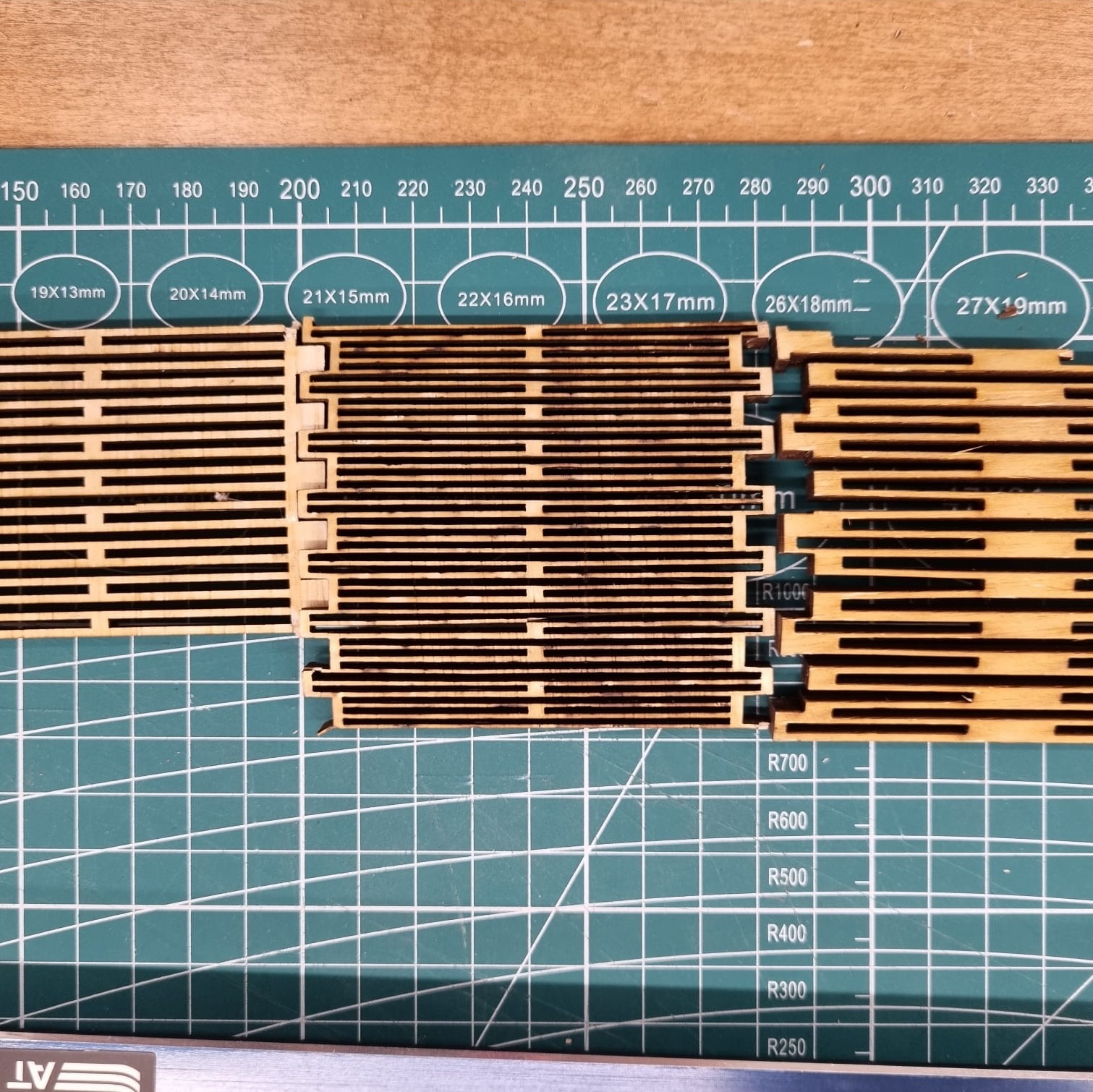
When facing a problem during the prototyping phase, it is important to approach it with a clear and rational mindset. In the case of the finger joints not being able to be cut on an angle from a vertical standpoint, I initially tried to force the design to work without considering other possibilities. However, after taking a step back and considering other options, I was able to adjust my approach and find a solution that worked better.
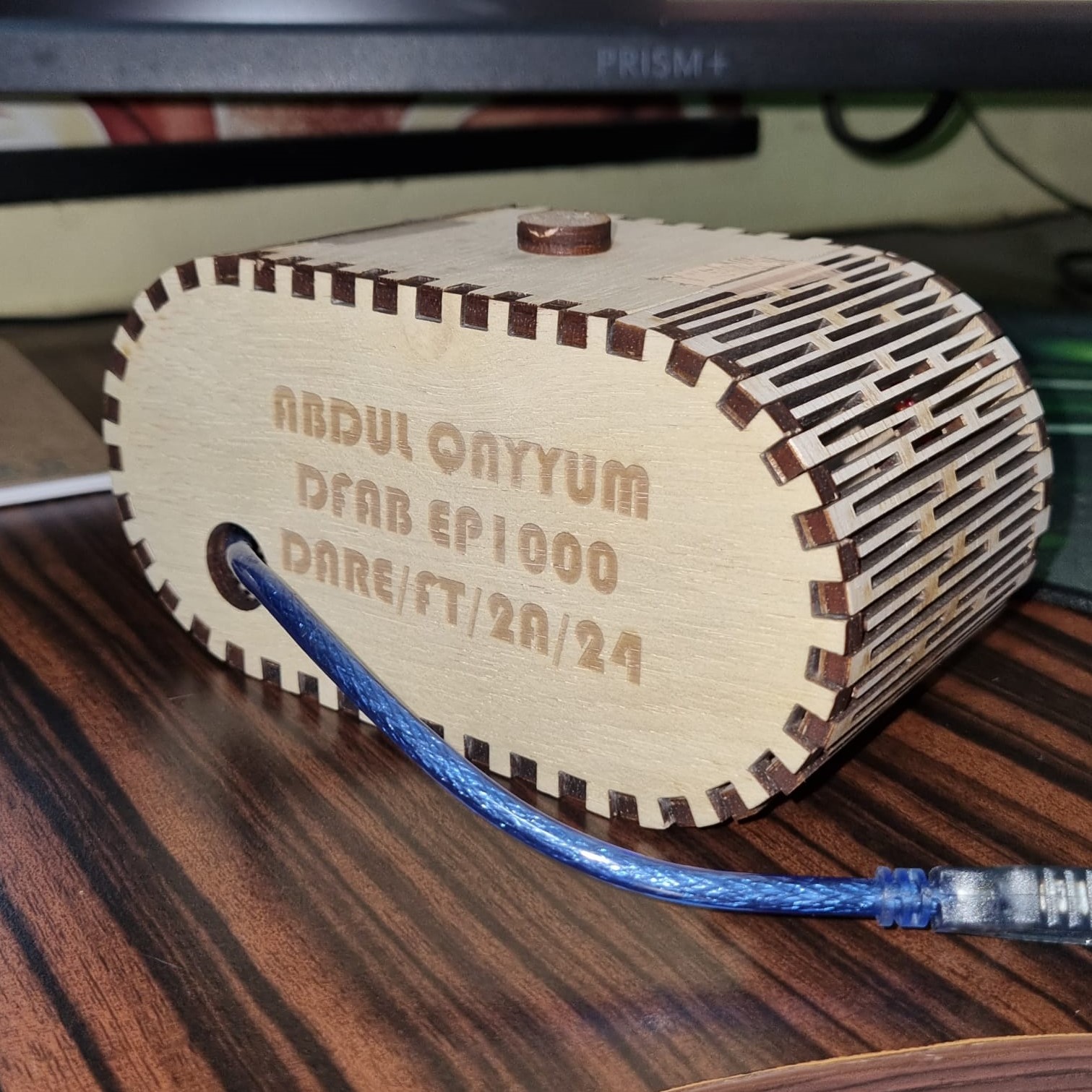
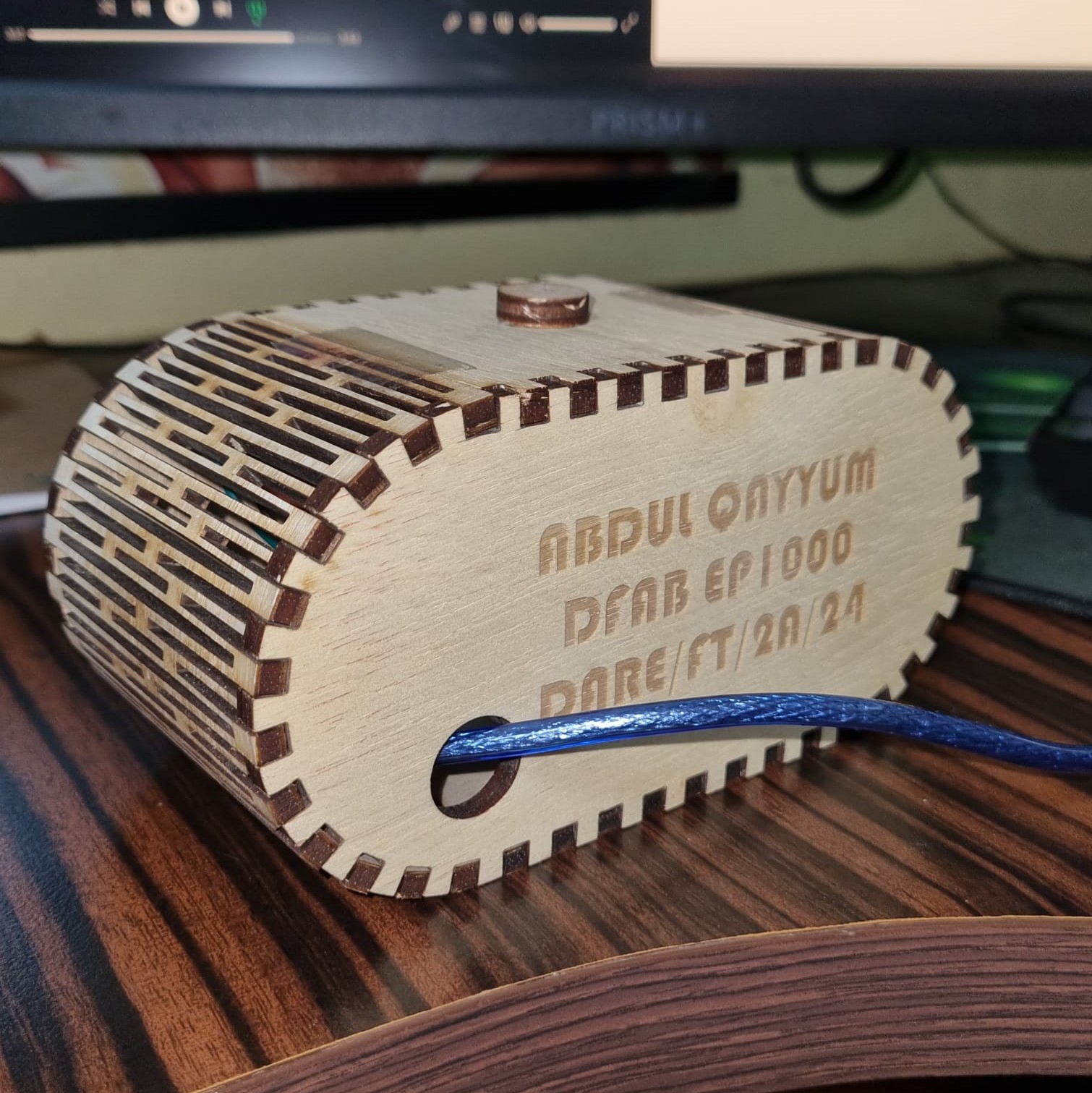
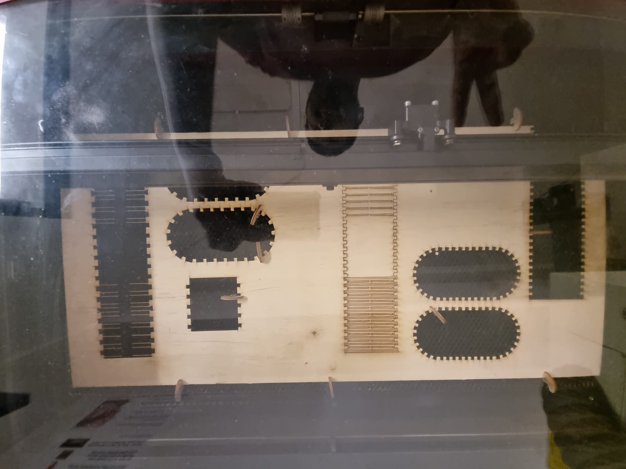
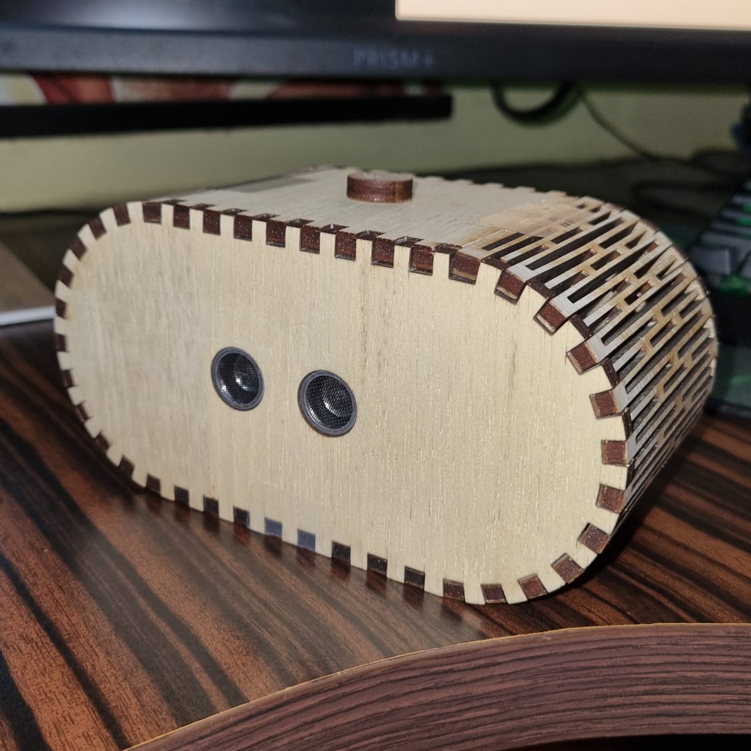
During the prototyping phase, I encountered several challenges while working on the hinge pattern for the project. In my first attempt, I found that the finger joint couldn't be cut on an angle from a vertical stand point, which made it difficult to attach to the case. Therefore, I had to rework the design and came up with the idea of using a curved hinge and elbow joint to create a more aesthetically pleasing design. However, my first rendition of the hinge pattern didn't fit the finger joint due to the taper nature, which was evident in the initial sketch. After realizing this, I made the necessary adjustments and tried again with a second rendition.
However, the second iteration was too weak as I had made excessive cuts, which made the joint more prone to breakage. So, I went back to the drawing board and came up with a third rendition of the hinge pattern. This time, I made sure that there were slits to the end of the joint that allowed it to bend while remaining strong enough to withstand the forces it would be subjected to.
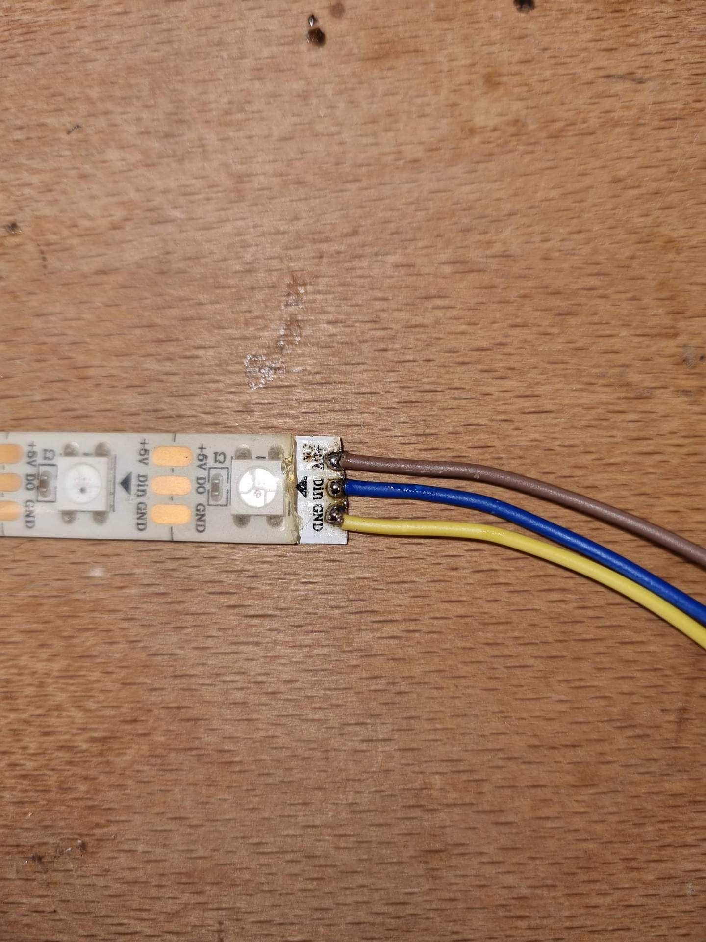
Another challenge during the prototyping phase was soldering the LED joints for the neopixel. As it had been a while since I last soldered, it took some time to get back into the rhythm of things. However, with patience and practice, I was able to successfully break and resolder the joints to ensure that the neopixel would function properly.
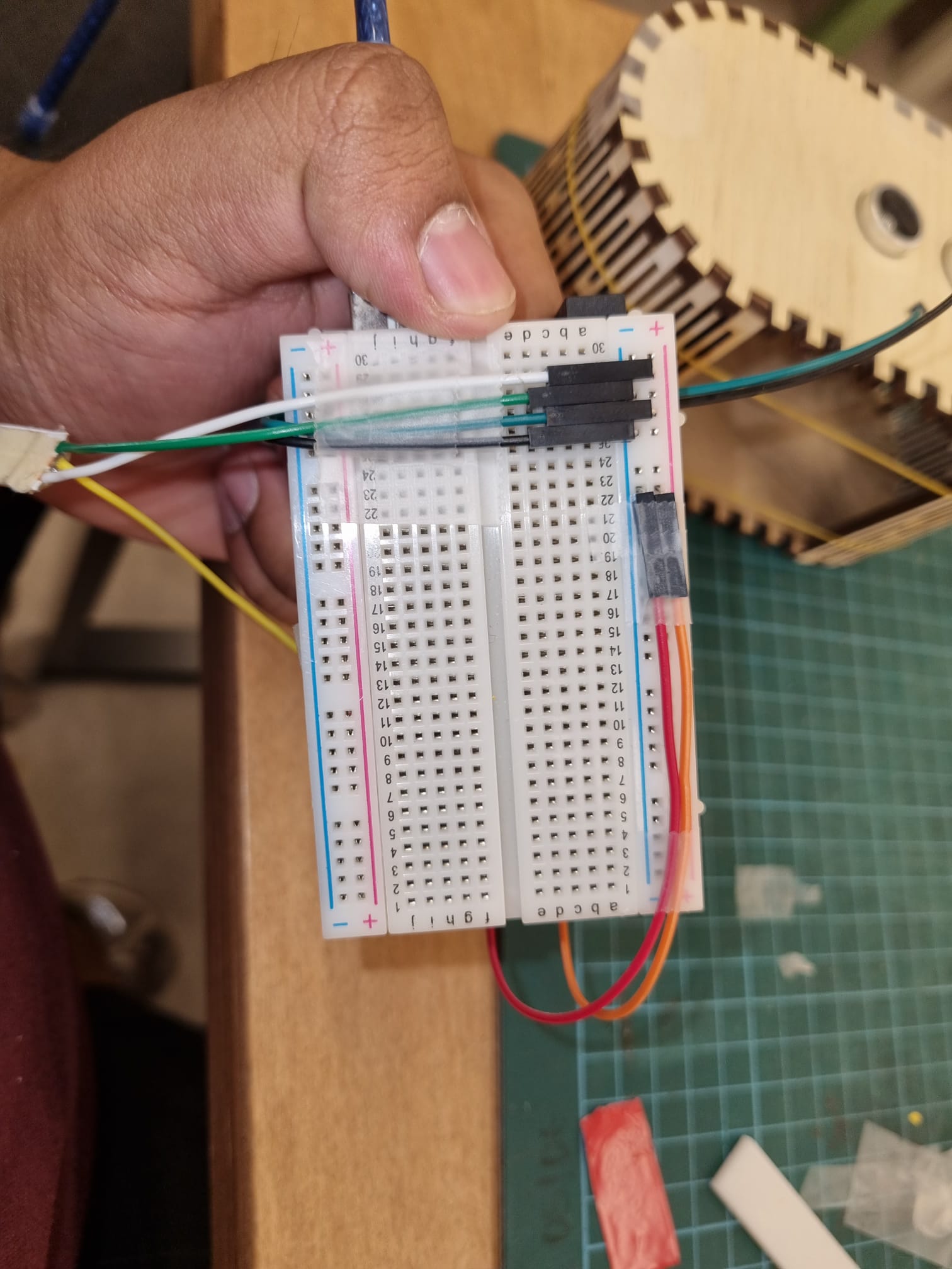
I also had to tackle the issue of space constraint. I wanted the final product to be compact and easily portable, so I decided to stack the breadboard and Arduino board on top of each other. This required careful planning of the pin layout, so that the pins could fit in between the two boards and the entire setup could sit flatly on the base of the case. I found that this arrangement was much more efficient in terms of space, but it also posed some challenges. For example, I had to make sure that the pins were properly aligned, and that there was no overlap or interference between them. Additionally, the stacked boards made it difficult to access the ports and connections on the bottom board.
Throughout the prototyping phase, it was important to approach each challenge with a problem-solving mindset and to not give up until a viable solution was found.
One of the learning points from this project is that taking a "try and refine" approach can be time-consuming and result in multiple iterations of a design. In retrospect, it would have been more efficient to adopt a "measure twice, cut once" approach. This would have saved time by ensuring that measurements and cuts were precise from the beginning, rather than requiring multiple revisions.
Another learning point is the importance of soldering skills. As I had not soldered in a long time, I encountered some difficulties with the LED joints for the neopixel. Improving soldering skills could be beneficial for future projects.
Additionally, the importance of testing and debugging was highlighted during this project. While the initial circuit design worked on the breadboard, it was necessary to adjust the layout and connections when transitioning to the final product. Testing and debugging at each stage could have prevented some of the issues encountered.
Finally, the importance of planning and organisation was demonstrated during this project. Planning and organizing the materials, tools, and workspaces before beginning the project could have made the process more efficient and reduced the number of revisions required.
Overall, there are several areas for improvement in future projects, including adopting a "measure twice, cut once" approach, improving soldering skills, testing and debugging at each stage, and planning and organizing materials and workspaces.
You can watch my 1 minute video here to see how my product works